
How a Pellet Stove Moves Fuel, Air, Exhaust, and Heat
Trace the fuel, combustion-air, exhaust and room-air paths, connect symptoms to systems, and verify replacements by model and serial range.
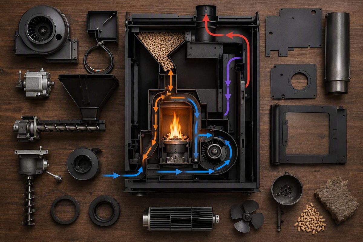
A practical first step is to identify which path is affected: fuel, combustion air, exhaust, or heated room air. Then consult the current manual for the exact model before cleaning, testing, or ordering a replacement.
The main components at a glance
A conventional pellet stove can be understood through four paths:
- Fuel path: Pellets move from the hopper through the auger into the burn pot.
- Combustion-air path: Air enters through an intake and passes into or through the burn pot.
- Exhaust path: Hot flue gases move from the combustion chamber through internal passages and out through the vent.
- Room-air path: Indoor air passes across heat-exchange surfaces and returns to the room warmer.
Typical pellet-stove system schematic
FUEL PATH
[Hopper] → [Auger + motor] → [Feed chute] → [Burn pot / grate]
                                                   ↓
                                            [Burning pellets]

COMBUSTION-AIR PATH
[Air intake] → [Internal air passage] → [Burn-pot openings] → [Fire]

EXHAUST PATH
[Firebox] → [Baffles / heat-exchange passages]
          → [Combustion or exhaust blower] → [Exhaust vent]

ROOM-AIR PATH
[Room] → [Convection or room-air blower] → [Air plenum]
       → [Heat-exchange surfaces] → [Heated air back to room]

CONTROL PATH
[Thermostat / user settings] → [Control board]
                              → auger, igniter, and blowers
[Pressure, temperature, door, or hopper switches] → [Control board]
This is a typical, not universal, layout. For example, an Englander manual documents a negative-draft arrangement that pulls combustion air through the burn pot and pushes exhaust through the vent. It also identifies separate combustion and convection blowers, a vacuum sensor, an igniter, and a control board. Those details apply to the named models, not automatically to every stove (Englander 25-PAH manual).
Compact glossary
| Term | Practical meaning |
|---|---|
| Burn pot / firepot / burn grate | The basket, tray, grate, or cupped area where pellets burn. The terms can overlap but are not always interchangeable. |
| Combustion blower / exhaust blower | The fan assembly supporting the combustion-air and flue-gas path. Confirm the manual’s terminology before treating the names as equivalent. |
| Convection blower / room-air fan | The fan that moves indoor air across heated surfaces and back into the room. |
| Hopper | The storage bin that holds pellets before they enter the feed system. |
| Auger | A screw-like shaft that moves and meters pellets toward the combustion area. |
| Igniter | An electric heating element that contacts fuel or heats air directed through the fuel bed. |
| Baffle | An internal plate or panel that directs hot gases through the intended heat-transfer or exhaust path. |
| Heat exchanger | Tubes, fins, walls, or other surfaces that transfer heat from combustion gases to room air. |
| Vacuum or pressure switch | A safety device that monitors whether expected draft or pressure conditions are present. |
Match the terminology to the labeled diagram and parts list for the exact appliance.
Fuel delivery and ignition: hopper, auger, motor, igniter, and burn pot
Pellets begin in the hopper. When the controls call for fuel, an electric motor turns the auger, which meters pellets through a feed path into the burn pot or grate. Air passes through or around the accumulated pellets, and the igniter helps establish a flame.
The auger system may include:
- An auger motor or gearmotor
- A shaft or complete shaft assembly
- Bearings or bushings
- Gaskets and mounting hardware
- A coupling
- Feed controls or control-board outputs
- A hopper-lid or other safety interlock
The control system can regulate fuel delivery by changing how and when the auger motor runs. Exact feed cycles and adjustments are model-specific and should not be borrowed from another stove.
The burn pot is the physical combustion area, but its construction varies. It may be a removable basket, perforated grate, cast tray, pot-and-liner combination, or complete assembly. Retail catalogs illustrate the commercial distinction between complete burn-pot assemblies, liners, and related service parts, but the manufacturer’s parts diagram determines how a particular appliance is assembled (pellet-stove parts catalog).
Substantial exceptions also exist. The St. Croix SCF-Revolution uses a rotating burn-pot drum and was offered in single- and dual-hopper configurations for approved multi-fuel operation. A fixed grate and single hopper are therefore common, not universal (St. Croix SCF-Revolution manual).
The igniter can operate in one of two broad ways. Some designs place the hot element in contact with or immediately beside the pellets. Others use it to heat air directed through the burn pot.
Useful cold-stove inspection points include:
- Burn-pot holes obstructed by ash or clinker
- Cracks, pitting, warping, or deformation
- Excess fines at the bottom of the hopper
- Foreign material mixed with pellets
- Pellet bridging that prevents fuel from settling
- Uneven or intermittent pellet delivery
- A liner or grate that is not seated as the manual shows
Do not jump from symptom to part. No ignition does not automatically mean a failed igniter. Pellet condition, fuel delivery, obstructed combustion-air openings, draft, safety switches, and controls can all affect startup. Likewise, no pellet feed does not prove that the auger motor has failed; an obstruction, open interlock, pressure problem, or control fault may prevent it from operating.
Airflow and heat: combustion blower versus convection blower
The two main blowers perform different jobs. The combustion or exhaust blower supports the route through which combustion air enters and flue gases leave. The convection blower or room-air fan circulates indoor air across the stove’s heated surfaces.
| Component | Alternate name | Air path and purpose | Symptoms to investigate |
|---|---|---|---|
| Combustion blower | Exhaust blower, draft fan | Supports flow from the intake through the burn pot and firebox toward the vent | Poor flame, dirty burn, pressure-related shutdown, ignition trouble |
| Convection blower | Room-air fan, distribution fan | Moves room air across heat-exchange surfaces and back into the room | Weak room airflow, low heat delivery, abnormal fan noise |
In documented negative-draft systems, the combustion blower pulls air through the burn pot and moves exhaust toward and through the vent. Some appliances use a vacuum or pressure switch to monitor the expected draft condition. This does not mean every stove has the same blower arrangement, pressure threshold, or switch logic.
The surrounding components matter as much as the motor:
- The air intake supplies combustion air.
- Burn-pot openings distribute air through the fuel bed.
- Baffles direct hot gases through internal passages.
- Heat-exchange tubes or surfaces absorb heat from those gases.
- The air plenum channels room air around heated surfaces.
- Impellers, fan blades, and blower wheels move air within their assemblies.
- Clean-out chambers provide access to areas where ash settles.
- The venting system carries exhaust outdoors.
If there is an active, credible flame but little warm air enters the room, investigate the convection side and accessible heat-exchange surfaces. If the flame is weak, lazy, or unstable—or the appliance reports a pressure-related shutdown—the broader combustion-air and exhaust route deserves attention.
Ash can restrict the burn pot, intake, internal passages, blower area, clean-outs, or vent.
Controls, sensors, safety switches, and seals
The control board coordinates stove operation. Depending on the design, it can manage ignition, auger operation, combustion and convection blowers, heat settings, startup timing, normal operation, and shutdown. It also interprets inputs from temperature, pressure, and closure switches.
A thermostat or heat-demand control is not the same as the control board. The thermostat requests heat; the board determines how the appliance responds. Manual feed-rate and fan-speed settings are also distinct because they modify operating commands within the manufacturer’s control logic.
Common safety and monitoring devices include:
- Vacuum or pressure switches, which monitor draft or exhaust conditions
- Low-temperature switches, which may indicate whether a sustained fire has developed
- High-temperature switches, which respond to excessive heat
- Door switches
- Hopper-lid switches, which may interrupt auger operation when opened
- Fuses
- Thermocouples or other model-specific temperature sensors
A documented PelPro system, for example, stops pellet delivery when its exhaust-pressure switch detects a plugged exhaust system, and opening the hopper lid activates a switch that stops the auger. These functions and thresholds are model-specific, but they show how an interlock can make a functioning auger or igniter appear defective (PelPro HSPP2 owner’s manual).
Do not bypass a safety switch. Manufacturer manuals restrict repairs to authorized procedures and warn against operating appliances contrary to their instructions. If a switch, its wiring, or the related control logic requires testing, follow the exact service documentation or use qualified service.
Gaskets need to be considered according to which air path they seal:
- Combustion- and exhaust-side seals may be found around the firebox door, door glass, burn pot, clean-out covers, and combustion blower. Damage or poor compression can interfere with the airflow or pressure conditions the stove was designed to maintain.
- Room-air-side seals, including any used around a convection blower or plenum, primarily affect circulation across the heat exchanger and delivery of heated air into the room unless the model documentation assigns them another function.
A gasket leak remains one possible cause, not a certain diagnosis based only on a lazy flame, dark glass, or weak heat. Switch locations, operating thresholds, sealing arrangements, and control logic all vary by appliance.
What to clean, inspect, or leave to a technician
There is no universal pellet-stove cleaning calendar. The current manual for the exact stove should set the schedule and identify which panels or assemblies an owner may remove.
| Area | Owner cleaning and inspection | Possible replacement | Professional-service boundary |
|---|---|---|---|
| Burn pot | Remove ash and clear permitted openings; inspect for cracks, pitting, warping, and blocked holes | Pot, liner, grate, gasket | Seized parts or unfamiliar designs |
| Firebox and baffles | Vacuum or brush as directed; check for ash restriction or a displaced baffle | Baffle or damaged panels | Removal that exposes restricted service areas |
| Heat-exchange surfaces | Scrape, brush, or operate the tube cleaner as directed; inspect for heavy deposits | Scraper or model-specific parts | Inaccessible internal passages |
| Hopper and fines | Remove fines as permitted; check for bridging, debris, or foreign material | Hopper seals or hardware | Auger disassembly or persistent feed trouble |
| Door and glass gaskets | Clean adjacent surfaces gently; inspect for loose, frayed, or flattened material | Correct gasket and specified adhesive | Uncertain fit or required door adjustment |
| Air intake | Clear accessible obstruction; inspect the cap and connections | Approved intake parts | Concealed or installation-related defects |
| Blowers | Vacuum accessible areas if authorized; note debris, noise, or damaged wiring | Motor, wheel, gasket, or assembly | Removal, electrical testing, or complex access |
| Clean-out areas | Empty and vacuum as directed; inspect covers and seals | Cover gasket or hardware | Undocumented disassembly |
| Exhaust venting | Inspect accessible sections as directed for buildup, loose joints, or damage | Listed compatible vent components | Disassembly, leakage, layout, or clearance concerns |
Commercial guidance may suggest frequent burn-pot attention and periodic inspection of the firebox, gaskets, blowers, and venting, but those intervals are examples rather than instructions for every appliance (Forge & Flame troubleshooting guide).
Useful findings include obstructed burn-pot holes, packed ash, pitting, cracking, deformation, soot buildup, loose or compressed gaskets, damaged connectors, and grinding, rattling, or squealing from a blower. Record what you see and hear without treating one observation as proof that an assembly needs replacement.
Before owner maintenance, follow the shutdown and servicing instructions in the exact manual. For example, an Englander manual requires its covered appliances to be unplugged and completely cool before maintenance and provides model-specific sections for the burn pot, baffle, blowers, vent, hopper fines, and gaskets (Englander installation and operation manual).
Refer electrical, control-board, sensor, motor, complex blower, and venting work to qualified service unless the appliance documentation expressly authorizes an owner procedure. Do not improvise replacement wiring or adapt generic controls; manufacturer instructions limit repair and replacement work to documented consumer procedures or authorized direction (PelPro HSPP2 owner’s manual).
Symptom-to-component checklist: investigate a system, not one part
Use this matrix to choose an inspection path, not to make a final diagnosis. Perform only cold-stove checks allowed by the exact manual.
| Symptom | Simple cold-stove checks | Possible component areas | When professional service is appropriate |
|---|---|---|---|
| No startup | Confirm power, thermostat demand, closure of the door and hopper, and a clean, seated burn pot | Outlet, fuse, thermostat, switches, control board, igniter, burn pot | Controls remain unresponsive or wiring damage is visible |
| No pellet feed | Check pellet level, bridging, obvious obstruction, and proper lid or door closure | Auger, motor, hopper switch, pressure switch, controls, draft path | The auger is jammed beyond the manual’s owner procedure or wiring is damaged |
| Pellets feed but do not ignite | Check burn-pot seating, air holes, ash, and pellet condition | Igniter, burn-pot airflow, combustion blower, intake, exhaust path | Failed ignition persists after permitted cleaning |
| Lazy flame or black glass | Inspect the burn pot, accessible intake, combustion-side gaskets, and clean-outs | Combustion blower, internal passages, vent, fuel, approved feed or air settings | The issue persists without an owner-authorized remedy |
| Weak room heat | Check room-air outlets and accessible heat-exchange surfaces | Convection blower, heat exchanger, combustion quality, controls | The fan fails or develops severe mechanical noise |
| Repeated shutdowns | Note when shutdown occurs; check fuel flow, closures, and accessible ash restrictions | Pressure and temperature sensors, feed system, airflow, control board | A safety control is suspected or shutdown continues after authorized checks |
The important distinction is between flame quality and heat distribution. A healthy-looking fire with poor room airflow points toward the convection route; poor combustion can reduce heat before the convection system has anything useful to distribute. Repeated shutdowns can also represent a safety device responding correctly to an airflow, temperature, closure, or fuel-delivery problem rather than a failed sensor.
If troubleshooting reaches wiring, controls, safety devices, inaccessible venting, or repairs not covered by the owner’s manual, stop the owner-level checks and obtain model-appropriate service. Manufacturer documentation warns that installation, servicing, and operation outside the prescribed instructions can create fire, electrical, and injury hazards (Englander installation and operation manual).
How to identify and buy the correct replacement part
The safest replacement search begins with the appliance, not with a photograph of the old part.
- Identify the exact manufacturer and model. Do not rely on the brand alone.
- Record the serial number and manufacture information from the appliance data plate.
- Obtain the current manual for that model and serial range.
- Find the exploded-parts diagram and parts list.
- Record the OEM part number, including documented revisions or superseding numbers.
- Verify the serial-number range and production-date notes.
- Compare the applicable physical, electrical, and mechanical specifications.
- Confirm compatibility through manufacturer documentation before relying on a retailer’s model finder.
On some appliances, identifying information may be on the rear panel, around the hopper-lid area, or behind the ash pan. These are possibilities, not universal locations. An Englander manual, for example, places its covered models’ identifying information on a safety tag beneath the hopper lid. Check the manufacturer’s documentation rather than dismantling panels at random.
Replacement-data worksheet
| Field | Record |
|---|---|
| Component name in manual | |
| Alternate or retailer name | |
| OEM part number / superseding number | |
| Stove make and exact model | |
| Serial number and applicable serial range | |
| Manufacture date or revision | |
| Dimensions and mounting pattern | |
| Voltage | |
| Wattage or amperage | |
| Motor speed and rotation, if applicable | |
| Shaft length, diameter, and profile | |
| Connector type and wire arrangement | |
| Gasket shape, thickness, and material | |
| Source of compatibility confirmation |
Igniters, auger motors, combustion and convection blowers, gaskets, control boards, thermocouples, switches, sensors, and burn pots are sold in OEM and aftermarket forms. Retail catalogs can establish that these categories are commercially available and help narrow a search by make and model, but they remain secondary to the manufacturer’s parts documentation (pellet-stove replacement-parts catalog).
Compare the OEM number, documented substitutions, serial range, dimensions, ratings, connectors, motor rotation, and included gaskets or hardware. For boards and sensors, also verify any documented production revision or OEM supersession.
Never order by appearance, generic category, or broad brand name alone. Use manufacturer manuals and official parts diagrams as the primary authority; treat retailer model finders as shopping aids.
Internal parts, installation hardware, and maintenance tools are not the same thing
“Pellet stove components” is often used loosely for everything sold near a stove. A clearer classification prevents a vent fitting, cleaning brush, or blower wheel from being mistaken for a complete internal assembly.
| Category | Examples | How to treat it |
|---|---|---|
| Internal operating components | Hopper, auger, burn pot, igniter, blowers, heat exchanger, control board, switches | Parts of the stove’s fuel, air, exhaust, heat, or control systems |
| Installation-system components | Pellet vent, appliance collar, clean-out tee, wall thimble, ceiling support or fire stop, outside-air hookup, floor protection | Parts of the installed system, not internal operating components |
| Replaceable subcomponents | Impeller, fan blade, blower wheel, bearing, shaft, motor, connector | Elements of a larger assembly; verify whether the manual services them separately |
| Seals and consumables | Door, glass, blower, burn-pot, and clean-out gaskets; approved sealants | Application-specific service items |
| Maintenance tools | Suitable vacuum equipment, rods, chimney brushes, scrapers | Tools used to maintain the system, not operating components |
| Decorative parts | Trim, medallions, panels, handles | Appearance or access parts unless the design assigns another function |
Retail collections sometimes group motors, brushes, and chimney rods under the same “pellet stove parts” heading. That merchandising category does not make a cleaning rod an operating component.
Vent size, outside-air requirements, clearances, supports, and permitted configurations are specific to the appliance and installation. Requirements documented for one Englander model—or any other individual stove—must not be treated as universal. The same caution applies to less common designs such as rotating burn pots, dual hoppers, additional draft fans, thermocouple-based controls, and approved multi-fuel modes.
The practical way to understand a pellet stove is to return to its four paths: fuel to the burn pot, combustion air to the fire, exhaust gases to the vent, and heated room air back into the home. Identify the affected path, clean or inspect only what the exact manual permits, and verify every replacement against the model, serial range, parts diagram, and specifications. Understanding the system makes troubleshooting more disciplined, but it does not replace model-specific instructions or qualified service for electrical, control, safety, or venting work.