
Diagnose a No-Start Before You Buy the Wrong Igniter
Published examples run from about 1.8-2.2 ohms to 99-109 ohms. Separate igniter faults from airflow problems, then verify exact electrical and physical fit.
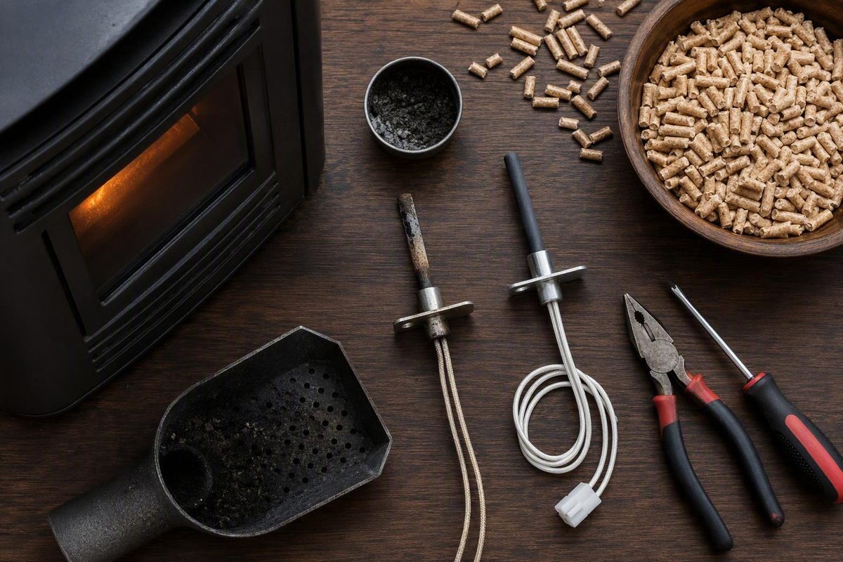
A failed startup does not automatically mean the pellet stove igniter has failed. The igniter is only one part of a sequence that also depends on pellet delivery, combustion airflow, a clean and correctly seated burn pot, intact seals, working sensors, sound wiring, and the control board.
Start with the stove cool and unplugged. Remove accumulated pellets and ash as directed by the appliance manual, inspect the burn pot and airflow path, and perform only de-energized electrical checks within your abilities. If replacement is justified, buy by exact model, OEM part number, voltage, wattage, resistance specification, dimensions, housing, connectors, and mounting position—not by brand name or appearance alone.
What the igniter does during a pellet-stove startup
During an automatic startup, the stove’s control system energizes the igniter. The igniter converts electrical energy into heat, remains active while pellets begin burning, and then switches off once combustion can sustain itself. The stove continues operating through controlled pellet feed and combustion airflow rather than keeping the igniter energized continuously.
Not every pellet stove transfers that heat in the same way:
- Direct-contact designs place the heating element where it can ignite or closely heat the fuel.
- Hot-air designs use the igniter to heat combustion air that flows into or through the burn pot and ignites the pellets.
This distinction matters during troubleshooting. In a hot-air design, an element can become hot but still fail to light the pellets if ash, blocked burn-pot holes, poor seating, an intake restriction, or weak combustion airflow prevents enough heated air from reaching the fuel. Stove & Grill Parts For Less describes both direct-contact and heated-air arrangements, rather than one universal igniter design (pellet-stove igniter operation).
A normal startup is a coordinated process:
- The control board initiates the startup program.
-
The exhaust or combustion fan establishes airflow.
-
The auger delivers pellets.
- The igniter heats either the pellets or the combustion air.
- Air moves through the burn pot and supports ignition.
A problem at any stage can look like “the igniter is not working.” A leaking door or ash-pan seal can interfere with draft. A dirty burn pot can block or divert hot air. A loose connector can interrupt the circuit. An auger problem can leave a functional igniter with no fuel to light.
Terms such as hot rod, cartridge, coil, and ceramic describe construction or heating technology. They are not compatibility categories. Two cartridge igniters may have different voltages, wattages, diameters, connectors, or insertion depths. Two ceramic elements may be intended for entirely different housings and airflow arrangements.
The central diagnostic rule is simple: a no-start is an ignition-system symptom, not proof that the heating element has failed.
Start safely and stop repeated failed ignition attempts
Before inspecting, cleaning, resistance-testing, or replacing an igniter:
- Complete the stove’s normal shutdown if it can do so.
- Disconnect the stove from its electrical supply.
- Let the appliance, igniter, burn pot, and surrounding metal cool completely.
- Follow the appliance manual before opening panels, moving internal parts, or removing accumulated fuel.
- Keep the stove unplugged throughout owner-level electrical work.
Do not begin merely because power has been disconnected. Wait until the igniter and adjacent parts are cool before touching or removing them. Pellethead’s technical guidance specifically directs users to keep a stove unplugged while testing or replacing the igniter or working on electrical components (igniter testing and replacement guidance).
Do not repeatedly reset a failed startup when unburned pellets are collecting in the burn pot. A delayed or unsuccessful ignition cycle may continue adding fuel. Remove excess pellets only as directed by the appliance manual, and determine why the earlier cycle failed before trying again. ComfortBilt similarly warns that leftover fuel or residue in the pot can contribute to a sudden “bang-to-life” event (ComfortBilt ignition-trouble guidance).
Keep owner testing de-energized. Do not improvise a power cord with exposed spade connectors and attach a loose igniter directly to a wall outlet. Stove & Grill Parts For Less explicitly characterizes that type of powered bench test as extremely dangerous (warning against improvised powered testing).
Stop owner-level troubleshooting and arrange qualified service when:
- Wiring is burned, brittle, broken, or frayed.
- Connectors are melted, badly discolored, loose, or corroded.
- The required voltage, wattage, resistance, or replacement part is uncertain.
- Access requires major disassembly not covered by the owner’s manual.
- A pressure system, sensor, relay, air pump, or control board is suspected.
- Diagnosis would require an energized voltage measurement.
- A venting or draft problem requires model-specific measurement.
- Smoke escapes from the appliance or vent during operation.
- The published procedure exceeds your tools, training, or electrical skills.
Retailer troubleshooting guidance likewise recommends professional assistance when the user is uncertain about electrical testing or repair. These stop conditions are especially important because model-specific electrical requirements and control circuits vary.
Use four symptom paths to narrow the fault
Observe only the normal startup behavior available from outside a properly reassembled stove, following the appliance manual. After noting the symptom, shut down the stove, unplug it, and let it cool before opening panels or inspecting components.
The four paths below synthesize common visual, airflow, wiring, and resistance checks described in pellet-stove troubleshooting guidance. They do not replace the model’s service procedure (five-step igniter troubleshooting overview).
| Startup symptom | What it may mean | Safe next action | When a technician should take over |
|---|---|---|---|
| Igniter stays cold | The element may be electrically open. Other possibilities include a disconnected lead, damaged wiring, missing power, a sensor or pressure-system interruption, or a control fault. | Once unplugged and cool, inspect accessible leads and connectors. If the manual permits, disconnect the igniter and compare its cold resistance with the exact specification. | Use a technician if resistance is within specification, wiring is damaged, the specification is unknown, or determining whether power reaches the igniter would require energized testing. |
| Igniter heats slowly or inconsistently | A degraded element is possible, but ash, poor airflow, incorrect positioning, a badly seated burn pot, or a loose or deteriorated connection can produce similar symptoms. | Clean the burn pot, intended air holes, and accessible igniter area according to the manual. Check positioning and accessible connectors, then compare cold resistance with the correct part specification. | Arrange service if cleaning and correct positioning do not restore reliable startup, the reading is ambiguous, or the power-delivery circuit must be evaluated. |
| Igniter gets hot but pellets do not light | Heat is being produced but may not reach the fuel effectively. Possible causes include clogged burn-pot holes, poor pot seating, intake or exhaust restrictions, compromised seals, weak combustion airflow, or incorrect pellet delivery. The element may also heat too slowly. | Stop the cycle if pellets accumulate. When the stove is cool and unplugged, clear the pot and its holes, verify seating, inspect accessible seals and openings, and confirm whether pellets were delivered normally. | Obtain service when the combustion fan sounds abnormal, venting is inaccessible, seals need repair, a pressure system is involved, or approved cleaning does not restore ignition. |
| A qualified technician or approved manufacturer diagnostic establishes that the igniter receives no power | The failure is upstream of the element. Depending on the model, the cause may involve wiring, a fuse, a switch, a sensor, a pressure control, a relay, or the control board. | Do not order an igniter merely because it remains cold. Consult the model’s wiring diagram and service documentation to identify the components controlling the circuit. | Energized measurements and control-board diagnosis belong with a qualified person unless the manufacturer provides an approved procedure appropriate to the user’s training and equipment. |
Visible glow is not a universal pass-fail test. Some designs may retain a cooler-looking tip or may not glow evenly along their full length. Conversely, visible glow shows only that the element is producing some heat—not that it heats quickly enough or that the required hot air reaches the pellets. Mountain View Hearth Products specifically notes that some igniters can have a cool tip (visual igniter troubleshooting).
The most useful observation is the complete startup sequence:
- Does the combustion fan start?
- Are pellets delivered?
- Do pellets arrive too early, too late, or in an excessive quantity?
- Does the igniter area warm at the expected point?
- Does smoke form without a flame?
- Does the control panel show an error?
- Does the stove stop feeding, continue feeding, or advance to normal operation?
That sequence helps distinguish a failed element from an airflow, fuel-feed, wiring, pressure-system, sensor, or control problem.
Rule out airflow, ash, and burn-pot problems before buying a part
Many igniters work by heating moving combustion air. That air must pass the element, travel through the intended channel, and reach the pellets through openings in or around the burn pot. If the path is obstructed, the igniter can become hot while the fuel remains below ignition temperature.
With the stove unplugged and completely cool, complete only those checks permitted by the manual:
- [ ] Remove unburned pellets left from the failed cycle.
- [ ] Clean ash and carbon from the burn pot.
- [ ] Clear the intended burn-pot air holes without enlarging or modifying them.
- [ ] Remove ash from the accessible igniter cavity or air channel.
- [ ] Confirm that the burn pot is installed in the correct orientation.
- [ ] Make sure the pot sits fully and evenly in its intended seat.
- [ ] Inspect accessible combustion-air intake openings for obstruction.
- [ ] Check approved exhaust passages and cleanout areas.
- [ ] Look for obvious buildup in accessible portions of the vent system.
- [ ] Inspect door and ash-pan gaskets for visible gaps, displacement, or damage.
- [ ] Confirm that doors, cleanout covers, and the ash pan close correctly.
- [ ] Inspect accessible igniter wiring and connectors.
- [ ] Confirm that suitable pellets reached the burn pot during the failed cycle.
Ash around the igniter can obstruct the heated-air path. Clogged pot holes reduce or redirect airflow into the fuel bed. Door or ash-pan leakage can also interfere with the pressure conditions on which the combustion system depends.
The combustion blower is another startup dependency. If it does not start, runs abnormally, or cannot move enough air through a restricted system, the igniter’s heat may not reach the fuel effectively. Pellet delivery matters just as much: no fuel means nothing to ignite, while continued feed during delayed ignition creates an accumulating fuel bed.
Pellethead’s Lopi and Avalon parts guidance lists burn-pot cleanliness and seating, door and gasket sealing, ash accumulation, exhaust venting, intake obstruction, and combustion-blower operation among the checks to make when ignition fails despite an apparently serviceable element (airflow-related ignition checks).
Leftover pellets and residue can cause two separate problems. Material in the wrong place may interfere with airflow, while a slowly developing ignition cycle may allow the auger to add more pellets before flame is established. That is why the stove should not simply be reset after each failed attempt.
Some manufacturers describe rough airflow-screening methods, such as observing whether paper is held against an intake. Treat any such method only as a model-specific preliminary clue. It does not provide a calibrated draft measurement and should not be generalized to other stoves.
Cleaning can resolve a symptom that looked like igniter failure. It cannot repair a cracked element, an open internal circuit, severely damaged leads, or an overheated connector. If airflow is restored but the disconnected igniter remains electrically open, replacement may still be justified.
Test continuity and resistance without treating generic numbers as universal
A multimeter can help evaluate a pellet stove igniter without energizing it. Keep the procedure de-energized:
- Shut down the stove.
- Unplug it and let it cool completely.
- Access the igniter only as directed by the appliance manual.
- Photograph or label the existing wire routing.
- Disconnect the igniter from the stove circuit as instructed.
- Inspect the element, leads, terminals, and connectors.
- Set the meter to resistance and confirm that the meter and probes respond.
- Place one probe on each igniter lead.
- Compare the result with the exact cold-resistance specification for that part.
An OL, infinite, or open-circuit indication generally means that the internal electrical path is broken. Before condemning the igniter, confirm that the meter is on the correct setting, the probes contact clean terminals, and the measurement is being taken across the element rather than through an unrelated open circuit.
Physical evidence can also support replacement:
- Burned or broken leads
- Severe bending or deformation
- Bubbling or swelling
- Cracks or impact damage
- Melted terminals
- Heat-damaged insulation
- A connector that no longer grips securely
Continuity means only that an electrical path exists. It does not establish that the igniter heats rapidly enough, reaches adequate temperature under operating conditions, is positioned correctly, or transfers heat effectively to the combustion air. A degraded or intermittent igniter can therefore show continuity and still produce unreliable startups.
Do not use 30–60 ohms as a universal pass range. That figure appears in general retailer guidance, but part-specific listings extend far outside it. Pellethead’s table includes approximately 1.8–2.2 ohms for one 12-volt GMG igniter and 99–109 ohms for one 137-watt Reliant igniter, along with many other model-specific ranges (part-specific igniter resistance table).
Use this hierarchy when interpreting a reading:
- Service documentation for the exact stove
- The owner’s manual, if it supplies the specification
- The original igniter’s part number and markings
- Manufacturer confirmation for the model and serial range
- Part-specific technical information from a reputable supplier
A reading can be judged only against the correct specification and test conditions. If the documentation calls for a cold test, let the igniter return to that condition before measuring it.
If a qualified person establishes that the specified power reaches the igniter during startup but the igniter remains cold, the element is a likely failure point. If power is absent, replacing the igniter is premature; diagnosis must move upstream through the applicable wiring, switches, sensors, pressure controls, relays, fuses, or control board.
Do not attempt energized measurements merely because an online guide lists a nominal voltage. Igniter supplies vary by model, and live testing should be left to a qualified technician unless the manufacturer provides an approved procedure suited to the user’s training and equipment.
Match the replacement by specification, not brand name alone
The safest starting point is the OEM part number for the exact model and, where relevant, its serial-number range. One brand may use multiple igniter designs across stove families or production periods. Even visually similar models can require different dimensions, connectors, housings, electrical ratings, or installed positions.
Use this worksheet before ordering:
| Compatibility field | Required information |
|---|---|
| Stove make | |
| Exact stove model | |
| Serial number | |
| Applicable serial-number range | |
| OEM igniter part number | |
| Original igniter markings | |
| Required voltage | |
| Required wattage | |
| Specified cold resistance | |
| Approved element material or design | |
| Overall element length | |
| Heated length, if specified | |
| Element diameter | |
| Required mounting depth | |
| Installed orientation or position | |
| Connector type | |
| Lead length and routing | |
| Housing or tube included? | |
| Existing housing reused? | |
| Bracket or retaining hardware | |
| Direct replacement or approved retrofit? | |
| Manufacturer confirmation or reference |
Prioritize the appliance manual, service documentation, original markings, and direct manufacturer confirmation. Treat phrases such as “fits most models,” “universal,” or “compatible with this brand” as leads to investigate—not proof of fit.
An element-only replacement supplies the heating element but may require the original housing, tube, or bracket to be reused. A complete assembly includes the element and a model-specific housing or mounting structure. Confusing the two can leave you with an unusable part even if the element’s electrical specification is correct.
For example, one Pellethead listing describes a 4-inch, 250-watt Lopi cartridge element that reuses the previous igniter housing, while another model-specific AGP listing includes the full housing assembly. These seller-provided examples demonstrate why package contents and installation arrangement must be checked; they do not prove compatibility outside the listed applications.
Also distinguish a direct replacement from a retrofit. Physical fit alone does not establish that a modification is approved or that the resulting installation will operate correctly.
ComfortBilt markets a ceramic igniter for most of several named product groups, but its listing does not provide a complete model-by-model compatibility table. The seller also says that some steel-to-ceramic installations may require retaining hardware or igniter-tube preparation (ComfortBilt ceramic replacement listing). That is a reason to obtain exact-model confirmation—not permission to file a tube, alter a bracket, or improvise a mounting arrangement.
Do not assume compatibility because a replacement:
- Slides into the existing tube
- Has the same general shape
- Uses similar-looking connectors
- Is advertised for the same brand
- Produces heat
- Is made from a newer material
- Has equal or greater wattage
Mounting depth and position are model-specific.
Understand ceramic, metal, and cartridge replacement claims
Ceramic and conventional metal or cartridge igniters can both be suitable when approved for the stove. Neither category is universally interchangeable or universally superior.
Evaluate a replacement in this order:
- Exact model and serial-range approval
- OEM or approved replacement part number
- Voltage
- Wattage and current requirements
- Cold-resistance specification
- Length and diameter
- Mounting depth and orientation
- Housing, bracket, and connector arrangement
- Compatibility with the stove’s airflow design
- Compatibility with the control board’s ignition cycle
Only after those requirements are satisfied should material, claimed heating speed, price, or expected service life influence the purchase.
Ceramic manufacturers and sellers often advertise faster heating, higher temperatures, reduced smoke, or longer life. Such statements may describe selected products under selected conditions, but they do not establish that any ceramic element will outperform the approved metal element in a particular stove.
For example, FKK reports that its PSx-6-240-B ceramic model reached 800°C in 40 seconds, compared with 3 minutes 40 seconds for an unspecified conventional metal heater. Because the manufacturer does not provide the comparison’s test protocol, sample size, operating conditions, or metal-heater model, the result does not support a universal conclusion about ceramic igniters (FKK promotional comparison).
Ceramic products also vary substantially. Retail listings include examples ranging from 250 to 350 watts and 88 to 147 millimeters in overall length. Those figures show that “ceramic” identifies a broad product category, not a fit specification (ceramic igniter size and wattage examples).
Do not pay a premium solely for a claimed ignition time, cycle count, durability advantage, or smoke reduction. First confirm that the claim concerns a part approved for the exact stove and installation. A faster element that has the wrong electrical specification, housing, position, or airflow relationship is not an upgrade.
Replace the igniter, verify the startup, and reduce repeat problems
Igniter access and mounting vary widely, so replacement is a model-dependent overview rather than a universal repair procedure. The appliance manual and the approved replacement-part instructions control.
A typical sequence is:
- Shut down, unplug, and cool the stove completely.
- Remove accumulated pellets as directed by the manual.
- Open only the panels identified in the instructions.
- Photograph the original wire routing, connectors, and igniter position.
- Record the installed depth if the approved procedure requires it.
- Disconnect the igniter leads without pulling on the wires.
- Remove the specified fastener, bracket, element, or housing.
- Compare the old and new parts before installation.
- Install the exact compatible element or assembly.
- Set the specified depth, alignment, and orientation.
- Use only the approved fasteners or retrofit hardware.
- Route leads as shown in the appliance or part instructions.
- Reconnect the correct terminals.
- Reinstall all panels, cleanout covers, gaskets, and seals.
- Confirm that no tools, loose hardware, or excess pellets remain inside.
Reuse an old housing only when the replacement instructions require it. Do not force a replacement into place, change mounting depth by guesswork, alter the tube, or add improvised washers and brackets. If the supplied part does not install according to the approved instructions, stop and recheck compatibility.
After complete reassembly, conduct the first startup under supervision and in accordance with the appliance manual. Watch for:
- Normal combustion-fan startup
- Expected pellet delivery
- Timely ignition
- A stable transition to normal combustion
- Smoke escaping from doors, joints, or panels
- Abnormal electrical or overheating odors
- Unusual fan, auger, or vibration noises
- Error codes or unexpected shutdown
- Fresh accumulation of unburned pellets
Stop the cycle if pellets continue accumulating without ignition. Do not repeatedly reset the stove in the hope that a larger fuel pile will eventually catch.
If the replacement heats but ignition still fails, return to system diagnosis. Recheck the burn pot, airflow path, combustion blower, seals, pellet delivery, and approved installation position. A new element cannot correct a blocked air channel, leaking ash pan, weak combustion airflow, or upstream control fault.
To reduce repeat problems:
- Keep the burn pot and intended air holes clear.
- Remove ash from the accessible igniter area.
- Seat the burn pot correctly after cleaning.
- Inspect accessible wires and connectors for damage or looseness.
- Maintain door and ash-pan seals.
- Keep approved intake and exhaust passages clear.
- Follow the manufacturer’s cleaning and vent-service schedule.
- Protect the stove and replacement parts from moisture.
- Investigate repeated failed starts instead of continually resetting the stove.
There is no dependable universal lifespan for a pellet stove igniter. Commercial estimates and owner reports range from a few years to substantially longer. A Hearth.com discussion, for example, includes estimates of three to five years as well as reports of igniters lasting about eight seasons, but the discussion is anecdotal and does not establish a standard service life (pellet-stove igniter lifespan discussion).
Frequent ignition cycling, thermal stress, debris, moisture, electrical problems, poor airflow, and incorrect installation may contribute to failure. None of that supports predicting a fixed number of starts or years for every stove.
The useful question is not simply whether the stove failed to light, but where its startup sequence broke down. Rule out ash, airflow, seating, sealing, and fuel-feed problems first. Use only unplugged owner-level electrical checks, compare readings with the exact part specification, and buy by model, OEM number, electrical requirements, dimensions, housing, and mounting details. If pellets accumulate, wiring is damaged, specifications are uncertain, or diagnosis requires energized circuits or control-board work, stop and use a qualified technician.
Frequently Asked Questions
Can a pellet stove igniter have continuity and still be bad?
Yes. Continuity confirms only that an electrical path exists through the element. It does not prove that the igniter reaches the necessary temperature quickly enough, transfers heat effectively, remains stable through the ignition cycle, or matches the required resistance specification.
A degraded or intermittent igniter may therefore show continuity but produce slow or unreliable starts. Compare its cold resistance with the exact model or part specification, inspect its condition and positioning, and rule out airflow and fuel-delivery problems before replacing it.
Why does the igniter glow but the pellets do not light?
A glowing igniter proves that it is producing visible heat, but not that enough heated air reaches the pellets. Possible causes include clogged burn-pot holes, ash around the igniter, incorrect burn-pot seating, intake or exhaust restrictions, damaged seals, weak combustion airflow, or improper pellet delivery.
The element may also heat too slowly despite glowing. Stop if pellets accumulate, then unplug and cool the stove before cleaning and inspection.
What resistance should a pellet stove igniter have?
There is no universal resistance value. Although general retailer guidance sometimes mentions 30–60 ohms, valid part-specific specifications can be far below or above that range. Published retailer examples extend from approximately 1.8–2.2 ohms for one 12-volt igniter to 99–109 ohms for one 137-watt igniter.
Measure the disconnected igniter when cool and compare the result with the exact manual, service documentation, original-part marking, or manufacturer specification. An OL or open result generally indicates a broken internal circuit after the meter setup, probe contact, and connections have been confirmed.
Can I replace a metal pellet stove igniter with a ceramic one?
Only when the ceramic replacement is approved for the exact stove model and installation. Verify the OEM or approved replacement number, voltage, wattage, cold resistance, dimensions, mounting depth, housing, connectors, airflow arrangement, control compatibility, and any required retrofit hardware.
A ceramic element that physically fits is not necessarily electrically or mechanically compatible. Do not alter an igniter tube, change mounting depth, modify wiring, or improvise brackets without exact-model manufacturer approval.
How long does a pellet stove igniter last?
There is no fixed service life. Longevity varies with the igniter design, stove controls, ignition frequency, installation, airflow, maintenance, moisture exposure, debris, and electrical conditions.
Commercial estimates and owner anecdotes range from a few years to much longer, but they do not establish a universal replacement interval. Diagnose the current symptom and test against the correct specification rather than replacing an igniter solely because of its age.